Inverting the Raspberry Pi Debug Probe's UART pins
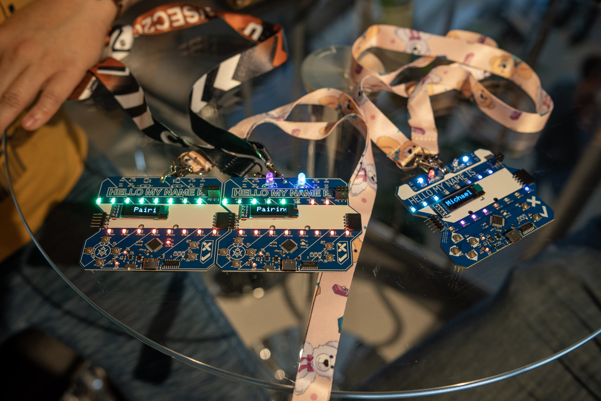
Last week I attended the NorthSec conference & CTF in Montreal. It was a great event, and I had a lot of fun! This year’s conference badge included a neat game where attendees could plug their badges together to earn points and unlock additional LED blinking patterns:
 Photo by Simon Carpentier is licensed under CC BY-NC 4.0
I wanted to reverse engineer the badge-to-badge communication protocol, and soon found out that it was asynchronous serial at 38400 baud, but with inverted polarity. While my Saleae logic analyzer happily decoded the inverted signal, my Raspberry Pi Debug Probe could not. I worked around the problem by building a couple inverters (one for transmit, one for receive) on a breadboard, and putting them between the badge and the Debug Probe. This worked, but it was cumbersome enough that I wanted to find a better solution.
After searching the web and digging through datasheets, I learned that the RP2040 chip’s GPIO pins can be inverted by setting GPIO control registers (specifically, the INOVER and OUTOVER fields in the GPIO*_CTRL registers). The gpio_set_outover and gpio_set_inover functions in the Raspberry Pi Pico SDK provide a convenient way to set these registers. It only took a couple lines of code to invert the UART pins in the Debug Probe firmware.
In case you’d like to try this out on your own Debug Probe, I’ve posted the compiled firmware on GitHub.