Firmware hacking
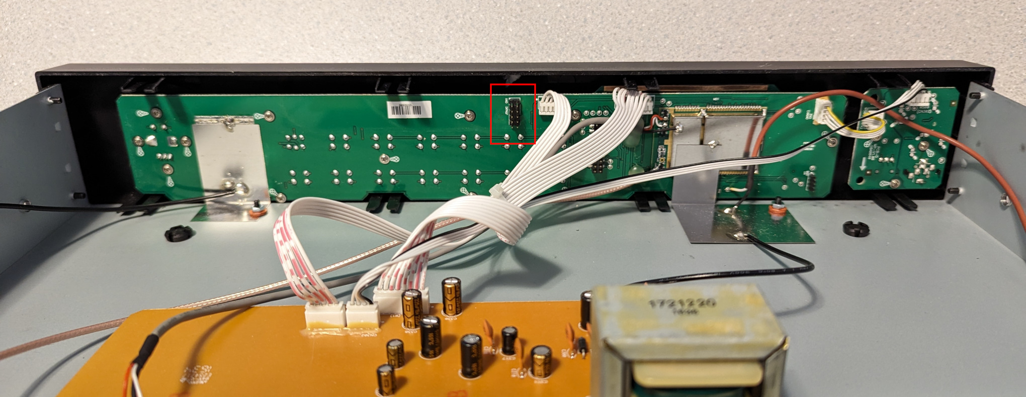
In a previous post, I extracted the firmware from a Sangean HDT-20 and modified it to add support for the MP11 mode, which is missing in most receivers. Unsurprisingly, the HDR-14 also lacks support for MP11, so I decided to take a crack at adding it. The first step was to open the radio and have a look at the circuit board:
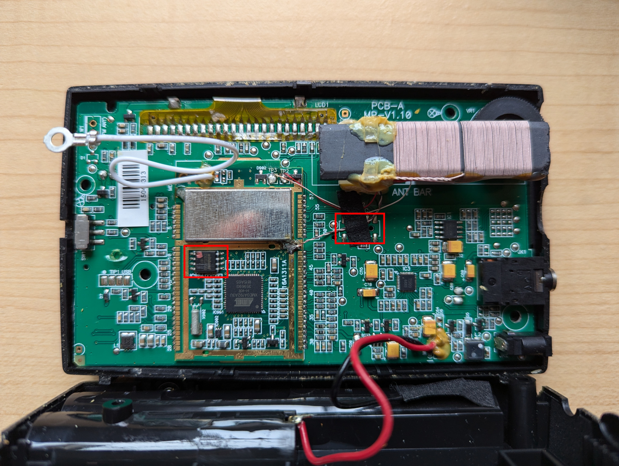
Like the HDT-20, this radio is based on an Atmel ATxmega192A3U microcontroller. Next to the microcontroller, a Winbond W25Q32JV 4 MB flash memory can be seen. (We’ll come back to that later.) And below the AM antenna, beneath a piece of tape, are 10 solder pads which appear to be a JTAG port. I confirmed with a continuity tester that the pads are in fact connected to the microcontroller’s JTAG pins, and soldered a 10-wire cable onto the pads so that I could connect my Atmel-ICE debugger.
It worked! Using the Microchip Studio Command Prompt on my Windows machine, I was able to extract the firmware with the following command:
atprogram -t atmelice -i jtag -d ATxmega192A3 read -fl -o 0x0 -s 0x30000 --format bin -f hdr14_app_section.bin
Back on my Linux machine, I converted the firmware dump to ELF and disassembled it:
avr-objcopy -I binary -O elf32-avr hdr14_app_section.bin hdr14_app_section.elf
avr-objdump -D hdr14_app_section.elf > hdr14_app_section.asm
In the disassembly, I found the same code fragment that I had patched in the HDT-20 firmware:
   19276:	60 91 ed 37 	lds	r22, 0x37ED
   1927a:	70 91 ee 37 	lds	r23, 0x37EE
   1927e:	80 e0       	ldi	r24, 0x00
   19280:	91 e3       	ldi	r25, 0x31
   19282:	0e 94 c6 7c 	call	0xf98c
   19286:	60 91 e9 37 	lds	r22, 0x37E9
   1928a:	70 91 ea 37 	lds	r23, 0x37EA
   1928e:	81 e0       	ldi	r24, 0x01
   19290:	91 e3       	ldi	r25, 0x31
   19292:	0e 94 c6 7c 	call	0xf98c
   19296:	60 91 e5 37 	lds	r22, 0x37E5
   1929a:	70 91 e6 37 	lds	r23, 0x37E6
   1929e:	82 e0       	ldi	r24, 0x02
   192a0:	91 e3       	ldi	r25, 0x31
   192a2:	0e 94 c6 7c 	call	0xf98c
   192a6:	60 e0       	ldi	r22, 0x00
   192a8:	70 e0       	ldi	r23, 0x00
   192aa:	81 e0       	ldi	r24, 0x01
   192ac:	95 e3       	ldi	r25, 0x35
   192ae:	0e 94 c6 7c 	call	0xf98c
As before, this code sets the FM_SEEK_BAND_BOTTOM (0x3100), FM_SEEK_BAND_TOP (0x3101), FM_SEEK_FREQUENCY_SPACING (0x3102), and FM_SOFTMUTE_SNR_ATTENUATION (0x3501) properties. This time, the address of the SET_PROPERTY routine is 0xf98c.
Like with the HDT-20, we’ll do the following:
- Replace the code that sets the
FM_SOFTMUTE_SNR_ATTENUATIONproperty with a jump to a free address. We’ll use address 0x2f000. - At that address, write some code that sets the
FM_SOFTMUTE_SNR_ATTENUATIONproperty as well as theHD_SERVICE_MODE_CONTROL_MP11_ENABLEproperty, then jumps back to address 0x192b2 (which is the address of the next instruction after the code fragment above).
We need only a single instruction to jump to address 0x2f000:
jmp 0x2f000
To assemble this and print the machine code in hexidecimal format, I ran the following:
avr-as -o patch1.o -mmcu=atxmega192a3 patch1.asm
avr-objcopy -O binary -j .text patch1.o patch1.bin
xxd -p patch1.bin
The final output is 0d940078, which we will write at address 0x192a6, replacing two ldi instructions.
The code to set the two properties and jump back to address 0x192b2 is:
ldi  r22, 0x00
ldi  r23, 0x00
ldi  r24, 0x01
ldi  r25, 0x35
call 0xf98c
ldi  r22, 0x01
ldi  r23, 0x00
ldi  r24, 0x00
ldi  r25, 0x9A
call 0xf98c
jmp  0x192b2
After assembly, the final hexidecimal output is 60e070e081e095e30e94c67c61e070e080e09ae90e94c67c0c9459c9, which we will write at address 0x2f000.
The final commands to patch the firmware using the Atmel-ICE debugger are:
atprogram -t atmelice -i jtag -d ATxmega192A3 write -fl -o 0x192a6 --values 0d940078
atprogram -t atmelice -i jtag -d ATxmega192A3 write -fl -o 0x2f000 --values 60e070e081e095e30e94c67c61e070e080e09ae90e94c67c0c9459c9
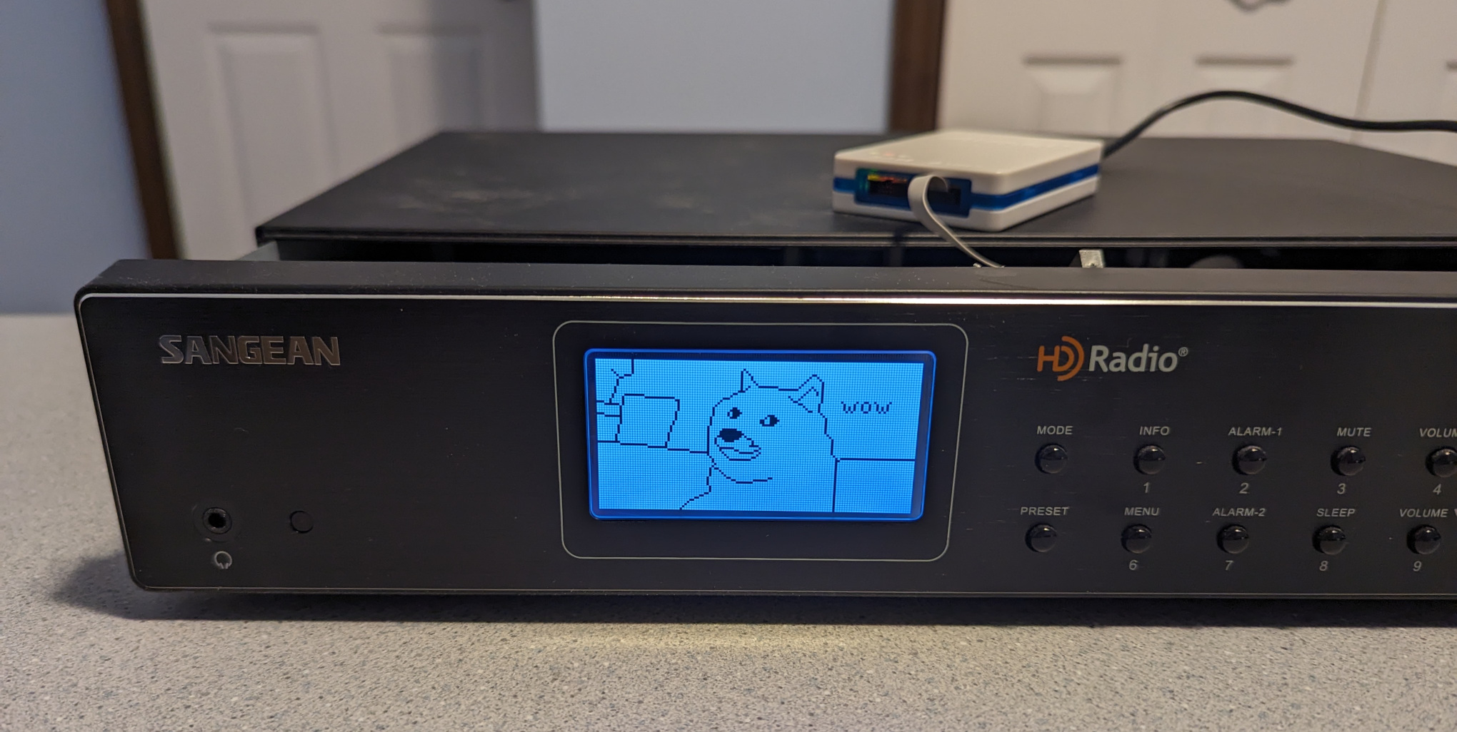
The patch works, and the radio can now receive all subchannels in an MP11 signal! 🎉
If desired, the original firmware can be restored like so:
atprogram -t atmelice -i jtag -d ATxmega192A3 write -fl -o 0x192a6 --values 60e070e0
atprogram -t atmelice -i jtag -d ATxmega192A3 write -fl -o 0x2f000 --values ffffffffffffffffffffffffffffffffffffffffffffffffffffffff
Note: These commands worked with my radio, which is running firmware HDR-14 P03. If your radio is running a different firmware version, it’s likely that the memory addresses will need to be changed.
Flash memory
Now let’s return to the Winbond flash memory chip mentioned above. According to the datasheet, it’s a serial NOR flash. The Raspberry Pi has a SPI interface, and it should be possible to connect to the chip using the flashrom utility.
After enabling the SPI interface in raspi-config (Interface Options → SPI) and connecting the Raspberry Pi’s GPIO pins to the flash chip (following the instructions in the flashrom wiki, and using the test clips that came with my Saleae logic analyzer), I was able to extract the flash memory:
flashrom -p linux_spi:dev=/dev/spidev0.0,spispeed=1000 -r hdr14_flash.bin
The binwalk utility didn’t identify anything in the dump, so I used its “entropy” mode to visualize the data:
binwalk -E hdr14_flash.bin
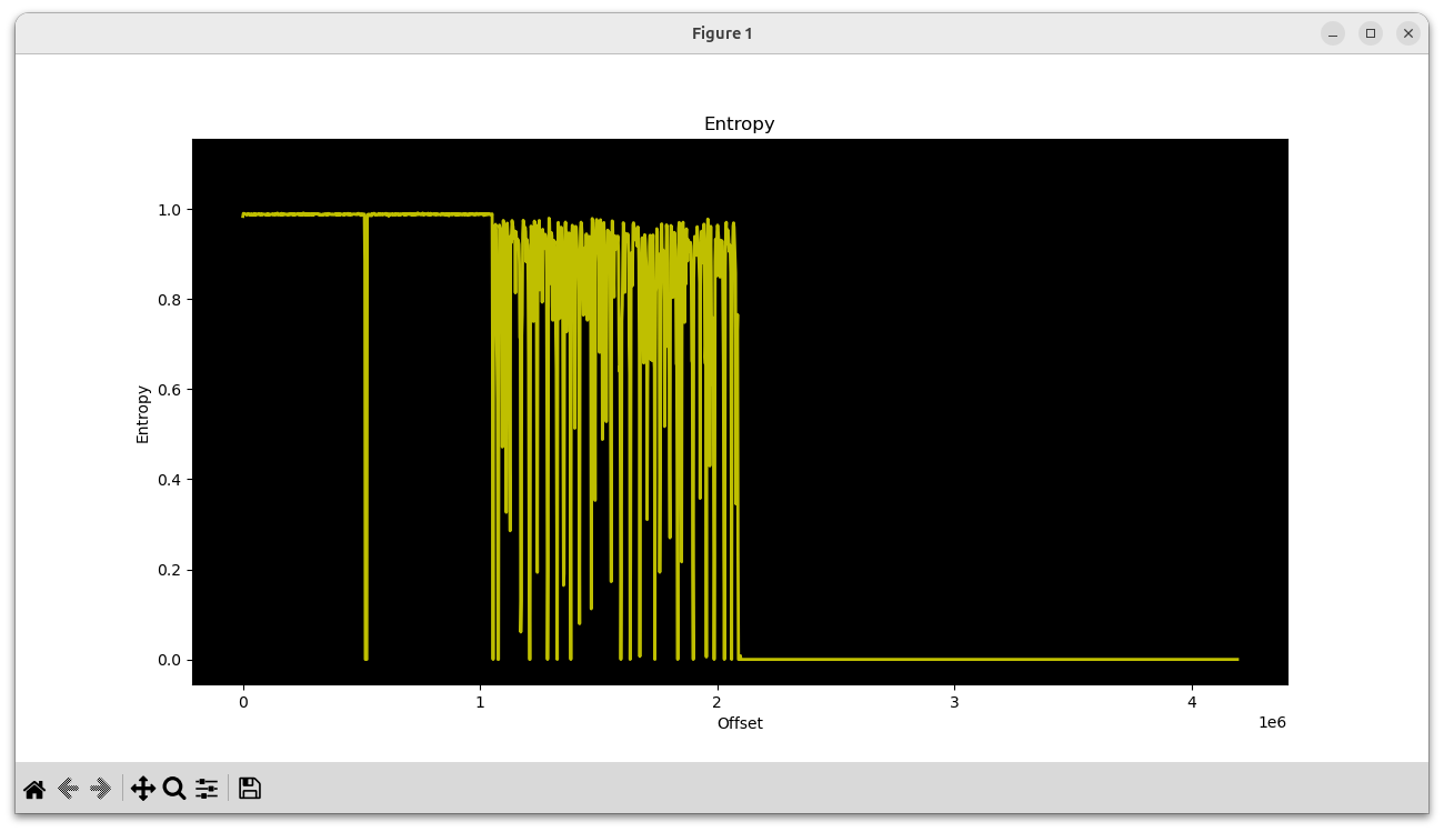
In the first megabyte, two high-entropy chunks can be seen. The next megabyte is a chunk with varying entropy, and the final two megabytes are empty.
With hexdump, we can see that the first two chunks are very likely firmware for the Si468x HD Radio receiver chip:
00000000  53 49 4c 41 42 53 5f 46  4c 41 53 48 70 de 07 00  |SILABS_FLASHp...|
00000010  01 00 00 00 00 00 00 00  00 00 00 00 78 56 34 12  |............xV4.|
00000020  00 00 00 00 30 00 00 00  3c 14 b3 48 2e 00 00 00  |....0...<..H....|
00000030  01 00 00 00 94 40 bf 67  fd 1b ae a5 17 ad 40 4f  |.....@.g......@O|
00080000  53 49 4c 41 42 53 5f 46  4c 41 53 48 cc 13 08 00  |SILABS_FLASH....|
00080010  01 00 00 00 00 00 00 00  00 00 00 00 78 56 34 12  |............xV4.|
00080020  00 00 00 00 30 00 00 00  3c 14 b3 48 2e 00 00 00  |....0...<..H....|
00080030  01 00 00 00 c7 aa 5a 38  37 0c 67 33 e1 79 bb f0  |......Z87.g3.y..|
It makes sense that there would be two of them; one for FM and one for AM.
Then beginning at offset 0x102000 is the mixed-entropy chunk:
00102000  28 00 00 00 00 58 00 00  00 40 00 00 00 40 00 00  |(....X...@...@..|
00102010  00 38 00 00 00 b8 00 00  00 90 00 00 00 40 00 00  |.8...........@..|
00102020  00 38 00 00 00 b0 00 00  00 a0 00 00 00 68 00 00  |.8...........h..|
00102030  00 78 00 00 00 40 00 00  00 48 00 00 00 c8 00 00  |.x...@...H......|
00102040  00 40 00 00 00 48 00 00  00 30 00 00 00 40 00 00  |.@...H...0...@..|
00102050  00 48 00 00 00 a8 00 00  00 98 00 00 00 a0 00 00  |.H..............|
00102060  00 78 00 00 00 80 00 00  00 50 00 00 00 50 00 00  |.x.......P...P..|
00102070  00 50 00 00 00 88 00 00  00 38 00 00 00 c8 00 00  |.P.......8......|
00102080  00 70 00 00 00 68 00 00  00 38 00 00 00 48 00 00  |.p...h...8...H..|
00102090  00 a8 00 00 00 78 00 00  00 48 00 00 80 0c 00 00  |.....x...H......|
001020a0  80 0c 00 00 21 00 29 00  29 00 2a 00 30 00 33 00  |....!.).).*.0.3.|
001020b0  39 00 42 00 4a 00 49 00  4e 00 50 00 53 00 5d 00  |9.B.J.I.N.P.S.].|
001020c0  5f 00 63 00 63 00 62 00  6c 00 6f 00 70 00 74 00  |_.c.c.b.l.o.p.t.|
001020d0  79 00 79 00 7b 00 88 00  85 00 84 00 8a 00 85 00  |y.y.{...........|
001020e0  80 00 80 00 79 00 77 00  71 00 6e 00 72 00 71 00  |....y.w.q.n.r.q.|
001020f0  69 00 60 00 5c 00 54 00  51 00 52 00 46 00 3b 00  |i.`.\.T.Q.R.F.;.|
I suspected this might be sound files for the emergency alert announcements (“Weather Alert”, “Safety Alert”, etc.) This turned out to be correct, as I was able to play back the audio by piping the data into aplay:
tail -c +1056769 hdr14_flash.bin | aplay -f S16_LE -r 16000
I heard “Alert, Down, 8, 80, Environmental Alert, …” There was a small amount of noise at the beginning, so I had a closer look and noticed that there appear to be 41 little-endian integers encoded at the start. Decoding them, we get:
40, 22528, 16384, 16384, 14336, 47104, …
40 is the number of recordings, and the numbers that follow are their lengths. With a bit of Python, the recordings can be dumped into WAV files:
#!/usr/bin/env python3

import struct
import wave

SOUNDS_OFFSET = 0x00102000
SOUND_NAMES = [
    "alert",
    "down",
    "8",
    "80",
    "environmental_alert",
    "fire_alert",
    "5",
    "4",
    "geophysical_alert",
    "hazmat_alert",
    "hd",
    "health_alert",
    "9",
    "90",
    "non_specific_alert",
    "off",
    "on",
    "1",
    "point",
    "preset",
    "rescue_alert",
    "safety_alert",
    "security_alert",
    "seek_down",
    "seek_up",
    "7",
    "70",
    "6",
    "test_alert",
    "3",
    "transportation_alert",
    "tune_down",
    "tune_up",
    "2",
    "up",
    "utilities_alert",
    "weather_alert",
    "0",
    "beep1",
    "beep2",
]

with open("hdr14_flash.bin", "rb") as f:
    data = f.read()

offset = SOUNDS_OFFSET

num_sounds = struct.unpack("<I", data[offset:offset+4])[0]
offset += 4

sound_lens = []
for _ in range(num_sounds):
    sound_lens.append(struct.unpack("<I", data[offset:offset+4])[0])
    offset += 4

for sound_len, sound_name in zip(sound_lens, SOUND_NAMES):
    sound_data = data[offset:offset+sound_len]
    offset += sound_len

    w = wave.open(f"{sound_name}.wav", "wb")
    w.setnchannels(1)
    w.setsampwidth(2)
    w.setframerate(16000)
    w.writeframes(sound_data)
    w.close()
In addition to the emergency alert messages, there are also recordings for voice prompts (“seek up”, “seek down”, “preset”, etc). I suspect these are unused, because the HDR-14 does not appear to have a voice prompt feature. It could be that the same flash memory is used in more than one Sangean model.
It would be fun to swap out the alert sounds with custom versions and write those back to the flash chip, but I’ll leave that project for another day.
]]>